 LcdTap |
Cases
LcdTap |
Cases
Capturing Screen of M5Stack CoreS3
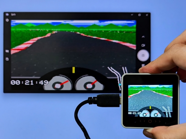
See also: LcdTap: M5Stack CoreS3 の画面をミラーリング/キャプチャする
Accessing the Chip Select Signal
The M5Stack CoreS3 does not have the CS signal exposed on the connector, so one of the following solutions is required.
Method1: Route CS signal to M-Bus
Requires modifying M5GFX.cpp and recompiling, but no
hardware modification is needed.
  void cs_control(bool flg) override
  {
    lgfx::Panel_ILI9342::cs_control(flg);

+   // GPIO5 を CS ピンに連動させる
+   lgfx::pinMode(GPIO_NUM_5, lgfx::pin_mode_t::output);
+   if (flg) {
+     lgfx::gpio_hi(GPIO_NUM_5);
+   } else {
+     lgfx::gpio_lo(GPIO_NUM_5);
+   }

    // CS操作時にGPIO35の役割を切り替える (MISO or D/C);

    // FSPIQ_IN_IDX==FSPI MISO / SIG_GPIO_OUT_IDX==GPIO OUT
    // *(volatile uint32_t*)GPIO_FUNC35_OUT_SEL_CFG_REG = flg ? FSPIQ_OUT_IDX : SIG_GPIO_OUT_IDX;

    // CS HIGHの場合はGPIO出力を無効化し、MISO入力として機能させる。
    // CS LOW の場合はGPIO出力を有効化し、D/Cとして機能させる。
    *(volatile uint32_t*)( flg
                           ? GPIO_ENABLE1_W1TC_REG
                           : GPIO_ENABLE1_W1TS_REG
                         ) = 1u << (GPIO_NUM_35 & 31);
  }
Method2: Wire directly
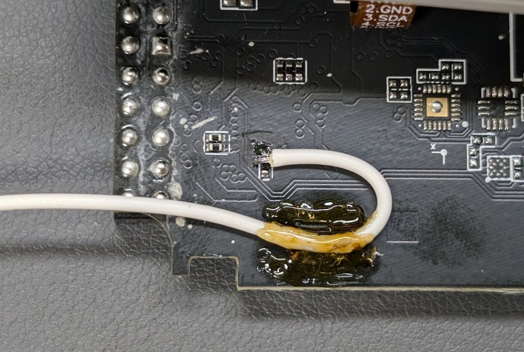
Wire directly to R49 on the back of the board: Hardware modification is required, but no software changes are needed.
Using LcdTap-Pico2 Universal
Connection
| LcdTap (Pico2) | Connection |
|---|---|
| GND | CoreS3’s GND |
| GPIO0 (RST) | Pico2’s 3V3 |
| GPIO1 (CS) | (See above instructions) |
| GPIO2 (SCLK) | CoreS3’s SPI_SCLK |
| GPIO3 (MOSI) | CoreS3’s SPI_MOSI |
| GPIO4 (DC) | CoreS3’s SPI_MISO |
Configuration
Load preset for M5Stack CoreS3.